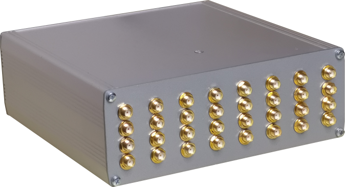
Some custom parameters that can characterize the device:
parameter PLL_FREQUENCY = 400000000;    //The pll frequency
parameter CLK_FREQUENCY = 10000000;    //The crystal frequency
parameter SIN_FREQUENCY = 50;        //The internal optional PSU frequency
parameter MUX_LINES = 1;        //Muxer lines
parameter NUM_LINES = 8;        //Lines per each Muxer line
parameter DELAY_SIZE = 2048;        //If 4 use quadrature sampling, if 0 use single sample quadrature sampling, else the delay FIFO size
parameter LAG_CROSS = 1;        //Lag lines size for live crosscorrelation
parameter LAG_AUTO = 1;            //Lag lines size for live autocorrelation
parameter RESOLUTION = 24;        //Resolution (count capacity) of each correlation/intensity counter
parameter HAS_LEDS = 1;            //Has this device output lines? (power switches or indicator or ramp generators sync?)
parameter HAS_CROSSCORRELATOR = 1;    //Has this device crosscorrelation capability?
parameter HAS_PSU = 0;            //Has this device a software PSU?
parameter HAS_CUMULATIVE_ONLY = 0;    //Has this device not on-edge counting?
parameter BAUD_RATE = 2000000;        //Communication port baud rate
parameter WORD_WIDTH = 1;        //Word width (greater than 1 when using ADC - must be in sync with the ADC ramp gener
parameter BINARY = 0;        //use binary packet transmission instead of ASCII
parameter USE_UART = 1;            //Use UART or SPI communication?
parameter USE_SOFT_CLOCK = 1;            //Limit usage of gated clocks
parameter MAX_ORDER = 2;            //Maximum crosscorrelation order
The generated SVF file can be downloaded to the device using urJTAG http://urjtag.org/
The cross-platform driver library: https://github.com/ahp-electronics/libahp-xc
To use the correlator try the GUI: https://github.com/ahp-electronics/xc-gui
The project runs at 10MHz and uses 2 Mbaud/second UART communication with the host initially
Here below is defined the communication protocol:
0x0d: Set integration parameters: bit 4 => enable capture, bit 5 => use external clock, bit 6 => reset timestamp when enabling capture, bit 7 => extra commands
0x01: select active line: first byte: bits [7:4] => length of command LSN, second byte: length of command MSN, next bytes: bits [7:4] => active line LSN first
0x02: led lines: extra commands => nibble indexer, bits [7:4] => power voltage value
0x03: if extra commands = 1 first byte: bits [7:4] => length of command LSN, second byte: length of command MSN, next bytes: bits [7:4] => cross-correlator order LSN first, if extra commands = 0 baudrate 57600 left-shifted by bits [7:4]
0x04: Set voltage: extra commands => nibble indexer, bits [7:4] => power voltage value
0x08: sampling clock tau =  first two byte: bits [7:4] => length of command LSN first, next bytes: bits [7:4] => value LSN first - if test[5:4] is 0 scan increment, if test[5:4] is 1 scan length if test[5:4] scan start channel if extra commands = 0 autocorrelator, if extra commands = 1 crosscorrelator.
0x0c: Set tests: extra commands => nibble indexer, bits [7:4] => test lines value - bit 1 => enable autocorrelation scan, bit 2 => enable crosscorrelation scan, bit 3 => BCM encoder on led 0 (pulse XOR by sampling clock), bits [5:4] => indexer of sampling clock tau
The count of pulses and correlation comes with an ASCII packet string ended with a 0x0d character
Each packet starts with a header with payload length indication, it is possible to change some parameters from the code
header
char 0: Nibble length of input lines hex digits [n0]
chars +n0: hexadecimal inputs quantity
char +1: Nibble length of sample size value hex digits [n1]
chars +n1: hexadecimal sample size value
char +1: Nibble length of delay channels hex digits [n2]
chars +n2: hexadecimal delay channels
char +1: Nibble length of live autocorrelator delay channels hex digits [n3]
chars +n3: hexadecimal live autocorrelator delay channels
char +1: Nibble length of live crosscorrelator delay channels hex digits [n4]
chars +n4: hexadecimal live crosscorrelator delay channels
chars +2 hexadecimal flags [bits: 0=live autocorrelator, 1=live crosscorrelator, 2=leds available, 3=cross-correlator, 4=Nyquist sampling, 5=Shannon sampling]
chars +4: hexadecimal value of the clock tau in picoseconds
payload
chars +lines*(sample size)#: pulses count of each line within the integration time
chars +lines*2*(sample size)#: autocorrelations real/imaginary count of each line within the packet time
chars +baselines*2*(sample size/4)#: crosscorrelations real/imaginary count of pulses of each line with others ones within the packet time
chars +lines*(n2)#: current delay channel in autocorrelator
chars +lines*(n2)#: current delay channel in crosscorrelator
chars +16: 8-byte timestamp of current packet
chars +2: 8-bit checksum of current packet
checksum
chars +2: 1-byte CRC of packet payload
EOP
chars +1: carriage return indicates end of packet
The packet time is determined by the baud rate and the packet size, the sampling rate is determined by the clock tau multiplied by the number of mux lines, raised by the clock tau power of two exponent.