Resources for researchers and hints or guides
- AHP XC Quantum correlators communication protocol
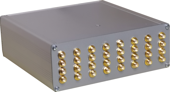
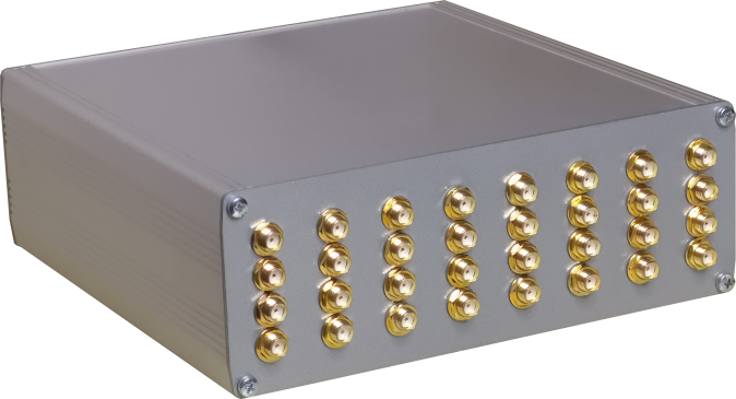
Some custom parameters that can characterize the device:
parameter PLL_FREQUENCY = 400000000;    //The pll frequency
parameter CLK_FREQUENCY = 10000000;    //The crystal frequency
parameter SIN_FREQUENCY = 50;        //The internal optional PSU frequency
parameter MUX_LINES = 1;        //Muxer lines
parameter NUM_LINES = 8;        //Lines per each Muxer line
parameter DELAY_SIZE = 2048;        //If 4 use quadrature sampling, if 0 use single sample quadrature sampling, else the delay FIFO size
parameter LAG_CROSS = 1;        //Lag lines size for live crosscorrelation
parameter LAG_AUTO = 1;            //Lag lines size for live autocorrelation
parameter RESOLUTION = 24;        //Resolution (count capacity) of each correlation/intensity counter
parameter HAS_LEDS = 1;            //Has this device output lines? (power switches or indicator or ramp generators sync?)
parameter HAS_CROSSCORRELATOR = 1;    //Has this device crosscorrelation capability?
parameter HAS_PSU = 0;            //Has this device a software PSU?
parameter HAS_CUMULATIVE_ONLY = 0;    //Has this device not on-edge counting?
parameter BAUD_RATE = 2000000;        //Communication port baud rate
parameter WORD_WIDTH = 1;        //Word width (greater than 1 when using ADC - must be in sync with the ADC ramp gener
parameter BINARY = 0;        //use binary packet transmission instead of ASCII
parameter USE_UART = 1;            //Use UART or SPI communication?
parameter USE_SOFT_CLOCK = 1;            //Limit usage of gated clocks
parameter MAX_ORDER = 2;            //Maximum crosscorrelation order
The generated SVF file can be downloaded to the device using urJTAG http://urjtag.org/
The cross-platform driver library: https://github.com/ahp-electronics/libahp-xc
To use the correlator try the GUI: https://github.com/ahp-electronics/xc-gui
The project runs at 10MHz and uses 2 Mbaud/second UART communication with the host initially
Here below is defined the communication protocol:
0x0d: Set integration parameters: bit 4 => enable capture, bit 5 => use external clock, bit 6 => reset timestamp when enabling capture, bit 7 => extra commands
0x01: select active line: first byte: bits [7:4] => length of command LSN, second byte: length of command MSN, next bytes: bits [7:4] => active line LSN first
0x02: led lines: extra commands => nibble indexer, bits [7:4] => power voltage value
0x03: if extra commands = 1 first byte: bits [7:4] => length of command LSN, second byte: length of command MSN, next bytes: bits [7:4] => cross-correlator order LSN first, if extra commands = 0 baudrate 57600 left-shifted by bits [7:4]
0x04: Set voltage: extra commands => nibble indexer, bits [7:4] => power voltage value
0x08: sampling clock tau =  first two byte: bits [7:4] => length of command LSN first, next bytes: bits [7:4] => value LSN first - if test[5:4] is 0 scan increment, if test[5:4] is 1 scan length if test[5:4] scan start channel if extra commands = 0 autocorrelator, if extra commands = 1 crosscorrelator.
0x0c: Set tests: extra commands => nibble indexer, bits [7:4] => test lines value - bit 1 => enable autocorrelation scan, bit 2 => enable crosscorrelation scan, bit 3 => BCM encoder on led 0 (pulse XOR by sampling clock), bits [5:4] => indexer of sampling clock tau
The count of pulses and correlation comes with an ASCII packet string ended with a 0x0d character
Each packet starts with a header with payload length indication, it is possible to change some parameters from the code
header
char 0: Nibble length of input lines hex digits [n0]
chars +n0: hexadecimal inputs quantity
char +1: Nibble length of sample size value hex digits [n1]
chars +n1: hexadecimal sample size value
char +1: Nibble length of delay channels hex digits [n2]
chars +n2: hexadecimal delay channels
char +1: Nibble length of live autocorrelator delay channels hex digits [n3]
chars +n3: hexadecimal live autocorrelator delay channels
char +1: Nibble length of live crosscorrelator delay channels hex digits [n4]
chars +n4: hexadecimal live crosscorrelator delay channels
chars +2 hexadecimal flags [bits: 0=live autocorrelator, 1=live crosscorrelator, 2=leds available, 3=cross-correlator, 4=Nyquist sampling, 5=Shannon sampling]
chars +4: hexadecimal value of the clock tau in picoseconds
payload
chars +lines*(sample size)#: pulses count of each line within the integration time
chars +lines*2*(sample size)#: autocorrelations real/imaginary count of each line within the packet time
chars +baselines*2*(sample size/4)#: crosscorrelations real/imaginary count of pulses of each line with others ones within the packet time
chars +lines*(n2)#: current delay channel in autocorrelator
chars +lines*(n2)#: current delay channel in crosscorrelator
chars +16: 8-byte timestamp of current packet
chars +2: 8-bit checksum of current packet
checksum
chars +2: 1-byte CRC of packet payloadEOP
chars +1: carriage return indicates end of packetThe packet time is determined by the baud rate and the packet size, the sampling rate is determined by the clock tau multiplied by the number of mux lines, raised by the clock tau power of two exponent.
Continue reading → - GT1 Firmware Upgrade process
The GT configuration utility allows to upgrade the GT1 and the AHP motor controllers with a new firmware.
Be sure to be connected to internet before proceeding.
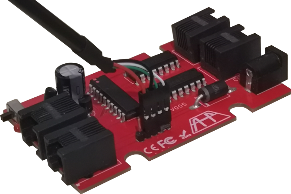
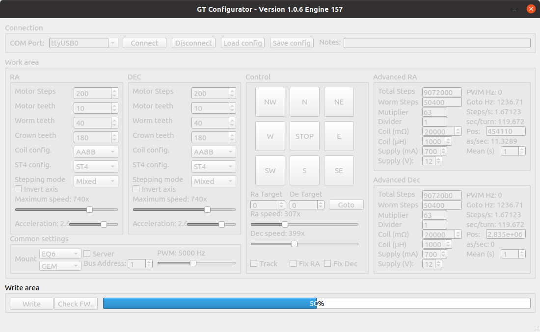
After running the configurator, click on “Check FW…”. The “Write” button will then unlock and will show the text “Flash”.
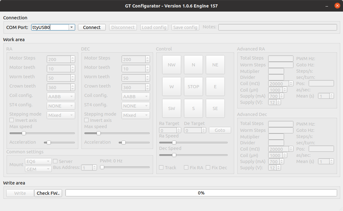
You have, then, to open the GT1 and reach the internal connector on the GT1 board:
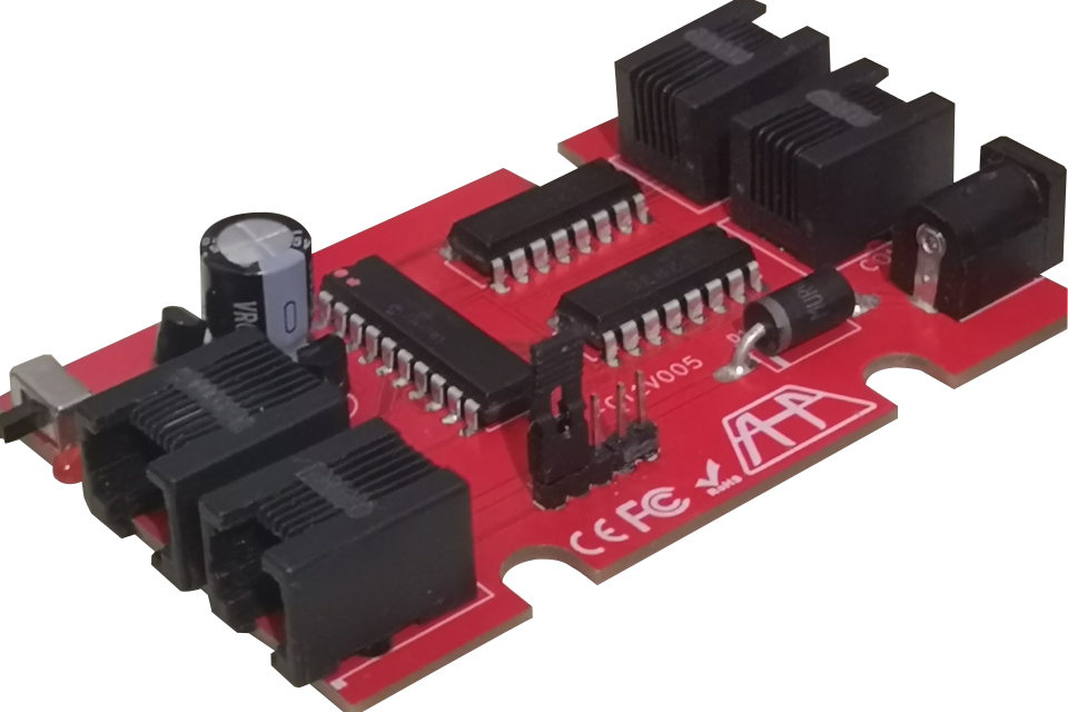
remove the Jumper from the ICSP connector and place the programming cable as in photo (the empty pin should replace half jumper:
Connect the usb programming cable to the PC. The PC should recognize the GT1 as “AHP Bootloader”. Click on “Flash”:
If nothing happens, click on “Check FW…” again, and retry.
After a firmware upgrade, replug the jumper as initially and that’s all.
Continue reading → - GT1 Configuration process
The GT configuration utility allows to program the GT1 and the AHP motor controllers with your custom mount parameters.
Once opened, the configurator shows two options of operation: connection to a GT1 controller or firmware upgrade.
Let’s start by describing the configuration of a GT1 controller:
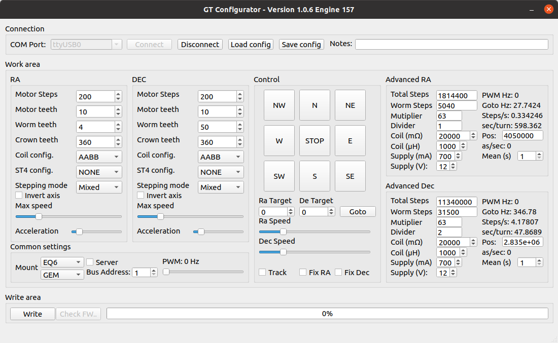
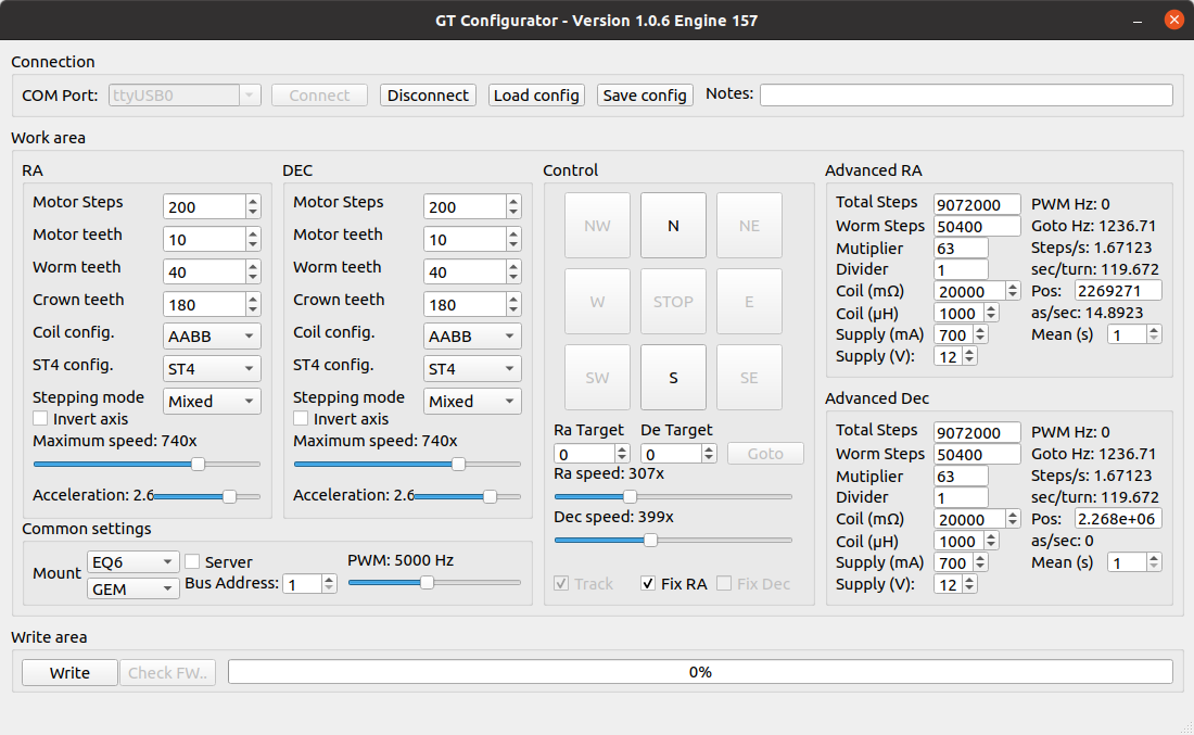
Select the COM port where the GT1 is attached and click “Connect”
After a while the controls will be unlocked and configuration will be possible
The RA/DEC motors reduction ratios can be configured by inserting their gears’ number of teeth. The configurator will found its optimal configuration and maximum step number by filling the right screen (Advanced RA and Advanced DEC) total steps and worm steps numbers.
You can choose to make the GT1 work in half-step or microstep modes by selecting the corresponding stepping mode. In mixed mode the planetary will choose which mode to use internally. Otherwise the GT1 will always work in a mode or another after the selection was done.
You can setup a maximum speed on each axis for gotos and slewing.
In microstepping mode the PWM frequency can be changed by using the trackbar. Different drivers can be used. We suggest to use the GTK5 kit for NEMA23 motors.
To program a GT1 click on “Write”
After writing there’s still a work to do: The sidereal tracking speed tuning.
Each configuration is not perfect at first write. The GT1 can tune-up its clock to fit all configurations for an optimal tracking speed.
Click on Fix RA and wait for a complete worm pulley turn.
After a working configuration will be found. You can save it by clicking on “Save config” and then loading it by clicking “Load config”
Continue reading → - Radar astronomy with the XC crosscorrelators
The XC crosscorrelators offer various opportunities for research and study.
One of these opportunities is to turn a radio antenna or a radio antennas array to a single or multichannel radar to study the moon or other NEOs.
To do this there are two possible configurations: one is to connect a transmitter to the external sampling rate output, the second is to connect the transmitter to the frame end output.
The transmitter will then emit a pulse each frame end or each sampling pulse synchronized with the readout clock of each antenna input.
The auto and cross correlation degree will then be relative to the reflection of the transmitted pulses from the object observed.
Using a single antenna will be very useful to determine the distance of the target of the observations, whilst in interferometer configuration there’s the possibility to draw a detailed map of the surface of the moon, for example or the shape of a smaller NEO like an asteroid or a meteor field during starfalling crossing dates.
Continue reading → - Superetherodyne reception with an XC correlator
The XC correlators offer reception bandwidths up to 200MHz. This feature allows them to obtain spectra and crosscorrelations with greater accuracy in comparison with other products.
A special feature of the XC correlators is the capability to work in superetherodyne mode by applying an oscillation signal to the external amplifier.
The superetherodyne mode can be used in radio quantum receivers, photomultiplier tubes, avalanche photodiodes, silicon photomultipliers, nanowire superconducting detectors and any quantum detectors connected to an XC correlator.
The standard oscillation frequency is set to 400MHz. The intermediate frequency remains the same as their normal bandwidth but the observed frequency is in offset by 400MHz, reaching out 600MHz and 1.67 nanoseconds timing resolutions on products like the XC8.
Continue reading → - Hint: observe an exoplanet with an XC correlator using reflex motion
Exoplanets orbiting around a star are observable in various ways.
Typically astronomers use techniques like photometry to determine if a planet transits in front of a star by observing the light curve of a variable star.
An instant drop-off of the luminosity of the star, and a drop-on of the self, mostly indicate that a planet transits in front of the observed star, expecially if this is observed periodically during an amount of time.
Another technique is called “reflex motion”:
This technique is often used on pulsars in radio astronomy. A pulsar emits very strong magnetic emissions in the radio wavelength regime.
A planet orbiting around a pulsar, when this is in the opposite side of the star (that means the pulsar is in middle way between the planet and Earth), reflects parts of the radiation of the pulsar.
These reflected radiations arrive delayed to an earth observer.
This event can be observed by an autocorrelator.
An autocorrelator like the XC series cross-correlators in autocorrelation mode can reach temporal precisions down to 5 nanoseconds.
The XC series crosscorrelators can decrease the temporal resolution time up to 65µs each step, so to coarse precision but acceptable in astronomy.
Light and radio emissions travel at the speed of light and each 3 nanoseconds travels to around 1m.
The autocorrelator shows the total emissions during an offset time, so if a planet reflects the light or radio emissions from a star, you can grab the actual perspective distance from the star itself to the planet with an extreme precision.
This obviously isn’t restricted to radio astronomy: a measurement can be done with optical sensors like photomultiplier tubes, avalanche photodiodes or silicon photomultipliers.
Continue reading →